

52,500 Kva. of Synchronous Condenser Capacity is Used for the Extensive High-Tension System of the Southern California Company — Functions of Condensers Discussed — How Equipment Is Operated for Maximum Economy
by J. W. Andree, Assistant Superintendent Department of Generation Southern Division, Southern California Edison Company

“Synchronous condensers are installed on electric transmission systems for three economic reasons: First, for reducing transmission losses by correcting for low power factor on the transmission lines; second, for voltage regulation at the receiving end of long transmission lines, and, third, for reducing the kva. load on generating equipment. The advisability of installing synchronous condensers, the finding of the proper location on a transmission system where they will be of the greatest advantage and the determination of the proper size of condenser to be used are problems requiring considerable study for proper solution. It is the present purpose to show how these problems were met by the Southern California Edison Company. Synchronous condensers are indispensable for voltage regulation at the receiving end of long high-voltage transmission lines having large electric capacity. A good illustration of this fact is given in the operation of the Big Creek line of this company. This is a two- circuit line, 241 miles (388 km.) in length, and is operated at 150,000 volts. The conductors are stranded aluminum cable wound on a stranded steel core, the total cross-sectional area being 683,500 circ. mils. At the Big Creek power houses there are four 17,500-kva. gen- orators, and at the receiving end, the Eagle Rock sub- station, there are two 15,000-kva. condensers for voltage regulation.
The inherent regulation of these lines alone, without terminal equipment, is indicated by the change from 10 per cent above power-house voltage at no load to 20 per cent below at full load. The electric capacity of the lines is 21,500 kva. with normal voltage at receiving end. By aid of the condensers the voltage at both ends of these lines is held constant at 150,000 volts up to about 30,000 kw. load, after which the voltage at the generating end is increased from 6 to 11 per cent at full load, depending upon the amount of single-line operation being done. There is usually a portion of one of the lines being used on other systems or out of service for repairs, tests, etc.
ALTERNATIVE METHODS OF VOLTAGE CONTROL
The advisability of using synchronous condensers on long transmission lines whose electric capacity is not large but upon which voltage regulation is poor because of the high resistance of the line is not so apparent. Here there are other alternatives which should be considered. Potential regulators may be installed at the receiving end to regulate the voltage. The particular advantages of these are that they may be obtained in small sizes to meet requirements of the load, that the first cost is low and that they require very little attendance. The disadvantages are that they lead up the transmission line, which is already overloaded, with lagging current which must be supplied and transmitted from generators or condensers installed at other parts of the system. Other ways to overcome poor regulation on lines of this kind is to increase the current-carrying capacity of the line by increasing the size of the conductors or to decrease the current required for the given load by increasing the voltage on the line. The objection to increasing the size of conductors as a means of correcting for poor regulation is the first cost and fixed charges. In the case of increased potential we have increased cost for transformers, insulators and line materials and also increased operating costs because of the greater number of failures in insulators and apparatus.
The advantages of using a condenser in this case are better voltage regulation, decreased line loss and decreased kva. load on generating equipment, transformers and lines. The objections are the high first cost and the increased operating attendance. The cost in each of these cases must be considered in conjunction with the probable load increase on the line and the capacity of and the lead carried on the generating equipment. The fact that some power is required to operate synchronous condensers must not be overlooked when figuring savings made possible by their operation. The advisability of installing synchronous condensers at heavy load centers on large transmission systems where the voltage is low during a portion of the day is quite apparent. The selection of the proper size of condenser, however, to be installed should receive considerable attention.
It is quite often advisable to install synchronous condensers for the purpose of reducing the kva. load on generating equipment, because it usually costs less to operate condensers near the load centers than it does to operate steam turbines or waterwheel-driven generators for the purpose of supplying kva. load to the system. Combinations of the above reasons for installing these machines make their use on large transmission systems almost indispensable.
Synchronous condensers should be installed as far from the generating plant and as near to the load as is possible, thus taking advantage of the reduction of losses due to power-factor correction over the greatest length of transmission line and through the step-down trans- formers. It is always advisable to install them at places where no additional transformer installations will be required for full-load kva. capacity for them.
OPERATION OF SYNCHRONOUS CONDENSERS
Having a transmission system with all the voltage regulators and synchronous condensers necessary to give good voltage regulation on the distribution system and for economical generation and transmission of the load, the next problem presenting itself is the most economical operation of the system as a whole. The voltage regulators will probably be in operation for twenty-four hours per day and 365 days per year, boosting the voltage during heavy load periods and bucking it during periods of light load, so they may be eliminated from the problem. It is sometimes advisable to operate all generators actually running on the system at full-load kva., regardless of the kw. load carried on them, to supply exciting current for the system, and condensers are only operated during the portions of the day when the exciting current furnished by the generators is inadequate or when the losses saved by condenser operation exceed the power required to operate them.
The Eagle Rock condensers of the Southern California Edison Company are operated twenty-four hours per day, bucking the voltage during the early morning hours when the load on the Big Creek system is less than 6000 kw. and boosting to full-load capacity during the daytime when there is a heavy load on the lines. All other condensers on this system are operated only at times when there is low voltage in the particular locality in which they are installed, or when the transmission losses saved by their operation exceed the power required to operate them, or when, by operation of these condensers, the kva. load can be decreased to such an extent that some of the generators may be taken out of service.
An interesting example of the saving possible in condenser operation as compared with the use of steam turbines for boosting voltage is the 6000-kva. condenser installed at the Los Angeles No. 3 station of this company. During the year 1913, before installation of the condenser, the cost of operating the 6000-kva. turbine for boosting voltage was approximately $14,000. The installation and operation of the 6000-kva. condenser reduced the operating expense to $8,000 per year, including the fixed charges, thus making a net saving of about $5,000 annually.
With the exception of the Eagle Rock condensers, no condensers on the system are operated with automatic field regulation. The flexibility of the transmission system is large, and in order to effect the greatest possible saving in transmission losses the condensers are either operated at full load or not at all. Economical or critical load curves are plotted for each condenser installation for determining the least load on the transmission line at which it is economically advisable to operate a condenser.
Fig. 1 is a power-factor diagram of the Edison system showing the electric capacity of the system, the power factor at which each of the generating plants is operating, the combined capacity of the condensers and their power-factor correction, and the average power factor of the load, which it will be noted is about 76 per cent. These power-factor diagrams are drawn from time to time for use in determining the best operating conditions of the system. In this connection it might be well to state that it is seldom advisable to operate any generating plant at a power factor higher than 95 per cent on account of the exciting current which it will furnish to the system, at a small expense of extra kva. on the plant. This is best shown in Fig. 2, which is a power-factor diagram of the Long Beach steam plant taken at the same time as in Fig. 1. Here it will be noted that with a load of 44,000 kw. and 51,800 kva. a wattless component of 27,500 kva. is furnished to the system by the small increase of 7800-kva. load on this plant. By this operation the Long Beach steam plant furnishes almost as much excitation to the system as the two Eagle Rock condensers combined, the only cost of supplying this extra kva. being the loss due to generating and transmitting this extra current to the load center, which is probably not more than the power required to operate these condensers at full load.
At the present time it is proposed to move one of the 2000-kva. condensers from the Colton substation to the Saticoy substation. Owing to the rapid increase of load on the Saticoy line the voltage regulation on this line is pour and the condenser will be of greater value at Saticoy than at its present location.
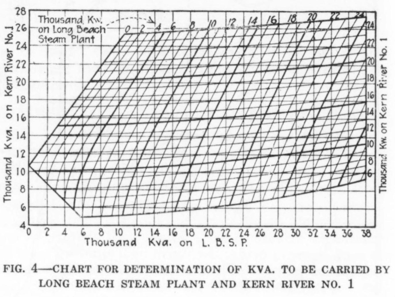
The problem of determining the most economical kva. load to be carried on the various generating stations feeding into a common system, upon which there are operated condensers of various capacities, is by no means a simple one. The method employed by this company for solution of this problem is illustrated by the chart shown in Fig. 4. This chart is calculated and con- structed so that the proper kva. load to be carried on the Kern River No. 1 plant and Long Beach steam plant, which will give the minimum line loss, may be read directly from the chart. This chart is for use in connection with operation of the 66,000-volt transmission lines from Kern River No. 1 and the Long Beach steam plant to the Los Angeles No. 3 receiving station and is calculated for the following conditions: System power factor, 70 per cent; total power-factor correction, 11,000 kva., made up of 5000-kva. line capacity and 6000- kva. condenser in operation at full load at the Los Angeles No. 3 station. To illustrate the method of using this chart let it be assumed that the total load to be delivered is 40,000 kw. and that the water conditions are such that the Kern River plant can furnish 16,000 kw. of this load, the balance, or 24,000 kw., to be carried on the Long Beach plant. The problem is to determine the proper loading of kva. on the two plants to give the minimum line loss. This may be determined by use of the chart as follows: Locate the 16,000-kw. line on the chart, using the scale on the right. Follow this line until it intercepts the 24,000-kw. line on the scale at the top of the chart; this locates a point on the original cross-section of the chart which gives the desired kva. to be carried on each plant. From this point follow the cross-section lines of the paper down to the lower scale, which will give 32,200 kva. to be carried on Long Beach steam plant, and follow the cross-section lines to the scale at the left, which gives 18,000 kva. to be carried on Kern River No. 1. Such charts should be constructed for various power factors and combinations of the principal plants feeding into the system.

In addition to the synchronous condensers, this company has on its system three 6000-kw. synchronous motor-generator frequency-changing sets in operation, changing the frequency of current from 50 to 60 cycles for interconnection with other companies operating in southern California. These units are operated with automatic voltage regulators in their field circuits and furnish considerable exciting current to both the 50- cycle and 60-cycle systems One of each of these units is located at Capistrano, Colton and Magunden. In addition to interconnection through frequency changers certain generating equipment in various plants is operated at other than its rated frequency directly for the benefit of and on the system of interconnected companies.
The following is a list of condensers (totaling 52,000 kva.) now in operation on the system of the Southern California Edison Company:

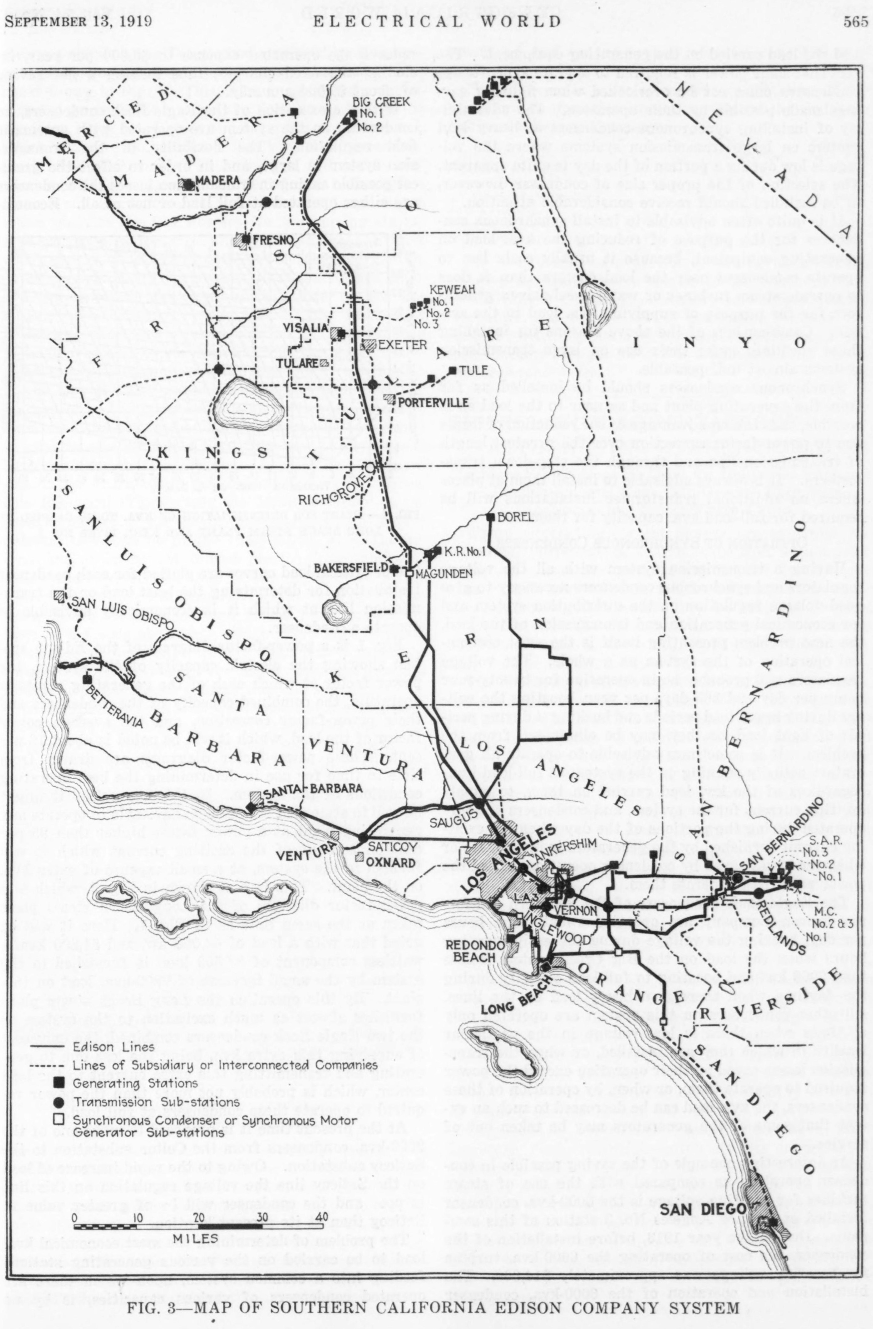
Fig. 3 is a map of a portion of southern California, showing the transmission system of the Southern California Edison Company, subsidiary and interconnected companies, also the location of generating stations, important switching stations, condenser stations and motor-generator stations. Fig. 5 is a photograph of one of the large condensers.
